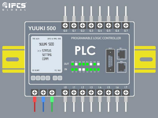
The main elements of industrial automation and control systems are programmable logic controllers (PLCs). PLCs may handle everything from a single motor to multiple intricate control systems, all at the stroke of a button. According to customer needs, planning and executing control applications requires PLC programming.
A PLC programme is a collection of textual or graphical instructions that represent the logic to be used in a particular industrial real-time application.
The PLC hardware of a particular manufacturer comes with a special PLC programming software that enables entry and creation of user application code, which can then be downloaded to the PLC hardware. The Human Machine Interface (HMI) as a graphical representation of variables is also guaranteed by this programme. When this programme is downloaded to the PLC and the PLC is switched to Run mode, the PLC starts to run the programme continually. Let’s first review the fundamentals of the PLC programming tutorial and its core ideas before moving on to the PLC programme.
Basics of PLC Programming
The PLC’s CPU runs two distinct programmes:
- The Operating System
- The User Program
-
The Operating System
All of the CPU’s activities, functions, and sequences that aren’t connected to control tasks are organised by the operating system. The OS tasks consist of –
- How to handle a hot restart and a warm restart
- Updating and producing the input and output tables for the process images
- The user programme is run
- Recognising the interrupts and calling them
- Taking care of the memory areas
- Getting in touch with programmable gadgets
-
The User Program
It is a synthesis of several operations necessary to carry out an automated task. This needs to be produced by the users and downloaded to the PLC’s CPU. The user software performs a variety of activities, including:
– Setting in motion the prerequisites for beginning the given task.
– All binary and analogue input signals are read and evaluated.
– Output signal specifications for all binary and analogue output signals.
– Handling errors and executing interrupts
There are several top PLC manufacturers that produce standard PLCs, ranging from tiny to high-end PLCs, in the current industrial automation business. Each and every PLC manufacturer has unique software that is used only for configuring and programming PLC hardware. But depending on the manufacturer, the PLC programming language varies. Some manufacturers use comparable programming languages, while others use different ones. Some of the PLC standard programming languages fall into one of the following two main categories, which are further divided into a number of categories:
-
Textual language
- Instructions List (IL)
– Structured Text (ST)
-
Graphical language
- Ladder Diagrams (LD)
- Function Block Diagram (FBD)
- Sequential Function Chart (SFC)
Due to their straightforward and practical programming capabilities, graphical programming languages are chosen by many users when compared to text-based languages for PLC programming. Each PLC software’s standard library contains all of the required functional blocks and functions. Timer, counter, string, comparator, numeric, arithmetic, bit-shift, calling functions, and other function blocks are examples of these function blocks.
Devices for PLC Programming
A PLC programme can be entered, modified, and troubleshooted using a variety of programming tools. Handheld and PC-based devices are included in these programming terminals. In the portable programming device technique, a connecting cable connects a proprietary device to a PLC. To enter, edit, and dump code into the PLC, use the device’s set of keys. These portable computers have a tiny display to make the programmed instructions apparent. Despite being portable and simple to use, these handheld devices only have a few features.
The PLC is most frequently programmed using a Personal Computer (PC) and the software provided by the manufacturer. We can execute the PLC programme on this PC in both online and offline modes, as well as edit, monitor, debug, and troubleshoot the PLC programme. The process of sending a programme to a PLC is depicted in the image above, where a programming cable is used to send programme code from the PC, which corresponds to a control application, to the PLC CPU.
Step-by-Step Guide for Ladder Logic PLC Programming
The type of standard manufacturer software tool and the type of control application determine the process for programming a PLC for a specific application. However, this article offers a straightforward method of developing control applications in PLC programming software, as shown below, in order to provide the students with some fundamental assistance. However, not every programming tool and control application can be used with this kind of programming.
Step 1 – Analyse and get an idea of the control application.
Step 2 – Create a flowchart and list all the conditions to determine the design.
Step 3 – Open and customise the PLC programming software.
Step 4 – Include the Necessary Rungs and Deal with Them.
Step 5 – Simulate it and check for errors.
Step 6 – Download the programme to the PLC CPU memory.
We hope the information provided is understandable and straightforward. With specific PLC software, such as RSLogix 500, Codesys, step 7, etc., it is also feasible to better grasp and know it.
For More Details Visit Our Website: https://ipcsglobal.com/mumbai-ipcs-global/
Our YouTube Channel: https://www.youtube.com/c/IPCSAutomationPLCSCADABMSCCTVCADTraining


0 Comments